
Custom Heat Pipe Design
Many factors go into the custom design of heat pipes: the heating load from the heat source, the designed purpose of the heat pipe (for example: to spread heat or exchange heat?), the heat pipe geometry (the evaporator and condenser section lengths, the length of the heat pipe, the number of bends and/or flattening, etc.), and the interface and attachment methods.
Once the inputs are known, then a new design can be created or an existing design could be validated, first using 3-D modeling techniques, and second using prototypes and thermal testing. After these steps are carried out, the design can go into production.
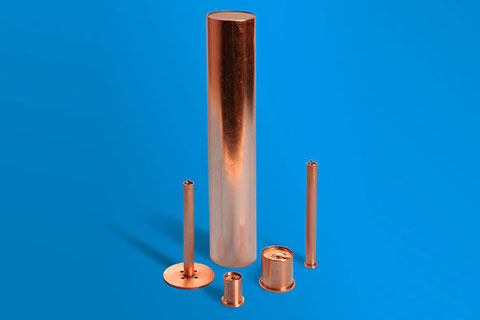
Heat Columns
DESIGN INPUTS
Each heat pipe can only carry a certain amount of energy per second. This means heat loads larger than 30 or 50 watts may require multiple heat pipes or a single heat pipe of larger diameter to move the heat from the heat source. Another thing to consider is the temperature of the heat source, as more restrictive temperature control methods require heat pipes with higher thermal capacity. Also, a heat pipe used to spread heat from a small heat source to a large heat exchanger will be designed differently than a heat pipe used to exchange the heat from the heat source to a dissipation point.
Heat pipe geometry can greatly affect the function of the heat pipe. Heat pipes with one or two large radius bends may have a small reduction of 5% or less of the heat pipe’s normal thermal capacity, but smaller radius bends will further reduce that capacity. Flattening heat pipes will also affect the thermal performance, as flattened heat pipes have greater surface area to accept heat and create better thermal contact with the heat source. Furthermore, the length of the heat pipe greatly affects its heat transport capacity, as well as the length of the evaporator section (the area of the pipe in contact with the heat source) and the condenser section (the area of the pipe in contact with the heat dissipation method). Other geometry considerations like orientation with respect to the direction of gravity also affect the thermal capacity of the heat pipe.
The method of contact between the heat pipe, the heat source, and other components of the thermal module is also important. The heat pipe contact with the heat source and heat diffuser has a certain level of thermal contact resistance. This can be lessened with thermal greases or thermal pads for less permanent bonds, and thermal epoxy or solder for bonds that require greater mechanical strength and permanence. Press-fitting the heat pipe into a fixture and/or machining the heat pipe surface to a desired flatness value requires a thicker heat pipe wall to withstand the mechanical stresses involved in those procedures.
Another critical design decision is the type of heat pipe wick that is employed. Each of Novark®‘s products uses a certain type of wick structure. The links below briefly explain each wick structure, and their various strengths and weaknesses.
[my_wick]
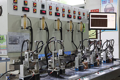
Heat Pipe Thermal Test Rig
THERMAL TESTING AND PROTOTYPES
Once the design inputs are decided, a heat pipe design is either created by Novark® or supplied by the customer. This is done through both engineering drawings and CAD-generated 3-D models. The 3D models are used to evaluate machining and manufacturing tolerances, and to program various CNC machines with finalized models.
Once the design has its tolerances cleared for manufacture, a set of prototypes is constructed and tested for their thermal performance. These thermal tests are the final validation before readying the design for mass production, and can be carried out either at Novark®‘s facilities or at the customer’s desired testing facilities. If the thermal performance is not as desired, Novark® will quickly and efficiently correct defects and refine the manufacturing process in order to create a final product that exceeds customer expectations.
Below is a table that shows the thermal performance of some straight sintered-wick heat pipes with no bends and at horizontal orientations to gravity at a variety of dimensions. This is only a set of reference data; please contact Novark® for a heat pipe design that is suited to your needs.
| 8mm Diameter Pipe at 0.3mm Pipe Wall Thickness | ||
|---|---|---|
| Pipe Flattened Thickness | Pipe Length | Maximum Heat Transfer |
| mm | mm | W |
| Round / ≥ 3.5 | ≥ 500 | ~13 |
| 450 | 17 | |
| 400 | 25 | |
| 350 | 37 | |
| 300 | 43 | |
| 250 | 50 | |
| 200 | 55 | |
| 165 | 60 | |
| 150 | 72 | |
| 450 | 17 | |
| ≥ 2.8 | ≥ 500 | ~10 |
| 450 | 12 | |
| 400 | 14 | |
| 350 | 16 | |
| 300 | 19 | |
| 250 | 30 | |
| 200 | 35 | |
| 165 | 46 | |
| 150 | 54 | |
| ≥ 2.5 | ≥ 500 | ~7 |
| 450 | 9 | |
| 400 | 11 | |
| 350 | 13 | |
| 300 | 16 | |
| 250 | 20 | |
| 200 | 27 | |
| 165 | 37 | |
| 150 | 43 | |
| ≥ 2.0 | ≥ 500 | ~5 |
| 450 | 7 | |
| 400 | 9 | |
| 350 | 11 | |
| 300 | 13 | |
| 250 | 16 | |
| 200 | 23 | |
| 165 | 27 | |
| 150 | 30 | |